
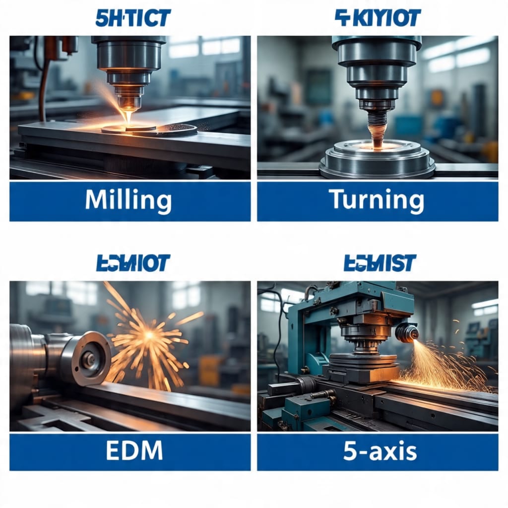
How to Choose the Right CNC Manufacturing Process for Custom Parts: Milling, Turning, EDM, or 5-Axis?
Right CNC Manufacturing Process

You have a design ready. You know the material, the tolerances you need, and roughly what the part should look like when it is finished. But then comes the question that slows engineers down more than they expect: which CNC machining process should you actually use?
Picking between CNC milling, CNC turning, electrical discharge machining (EDM), and 5-axis machining is not just a technical decision. It shapes your lead time, your per-part cost, your surface quality, and whether the geometry you designed is even achievable. Get it right and everything flows. Get it wrong and you are looking at rework, delays, and a quote that does not make sense.
This guide walks through each process clearly, explaining what they do well, where they fall short, and exactly when to use one over another. If you are an engineer or product designer comparing CNC options before requesting a quote, this is the resource you need.
What Is CNC Machining and Why Does Process Selection Matter?
CNC stands for computer numerical control. It is a subtractive manufacturing method where a machine removes material from a solid block or bar using programmed tool paths. The machine reads instructions written in G-code, derived from a CAD model, and executes cuts with speed, precision, and repeatability that no manual process can match.
What many people overlook is that "CNC machining" is not a single process. It is a family of processes, each built around different mechanics, different cutting dynamics, and different strengths. Choosing the wrong one does not just cost you money; it can make a part impossible to manufacture as designed.
Here is what process selection directly affects:
Part geometry feasibility - Some shapes simply cannot be produced by certain processes. Deep internal pockets, sharp internal corners, and features that cannot be accessed from a standard cutting direction all require specific approaches.
Achievable tolerances - Every process has a natural accuracy range. Pushing a process beyond its practical limits slows everything down and drives cost up.
Surface finish quality - The texture left on a part depends heavily on how material is removed. Some processes leave smooth, almost polished surfaces by default. Others leave visible tool marks that require secondary finishing.
Lead time - Setup complexity, number of operations, and machine programming time all vary between processes. These factors directly affect how quickly you receive your parts.
Cost per part - Machine hourly rates, setup time, tooling wear, and how many operations are needed all feed into the final quote.
Understanding these trade-offs before you finalize your design gives you far more control over all of them.
CNC Milling: The Workhorse for Prismatic and Complex Parts
How CNC Milling Works
In CNC milling, the workpiece is held stationary in a vise or fixture while a rotating multi-point cutting tool moves through the material. The cutter removes material along programmed paths across the X, Y, and Z axes. Standard 3-axis milling machines move the tool in three linear directions. More advanced configurations add rotation and tilt, which is where 4-axis and 5-axis milling come in.
The range of operations available on a milling center is broad. Face milling flattens top surfaces. End milling cuts slots, pockets, and profiles. Drilling and tapping create holes and threaded features. Contouring traces curved paths across a surface. One machine can handle all of these in a single setup when properly programmed.
- What CNC Milling Does Best
Milling is the natural choice when your part has:
Flat surfaces, pockets, and slots - Any part with flat faces, recesses, or channels falls directly in the strengths of a milling center. Brackets, housings, plates, enclosures, frames, and mold bases are classic examples.
Multi-face features - When a part needs work done on several sides, a milling setup with proper fixturing handles this well. With 4-axis or 5-axis capability, multiple faces can be machined in a single setup without repositioning the workpiece by hand.
Complex 3D geometry - Sculpted surfaces, organic contours, and freeform profiles that cannot be described by simple cylindrical or flat geometry require milling. Think of impeller housings, mold cavities, orthopedic device bodies, and aerospace structural components.
Prototypes and low to medium volumes - Milling centers are flexible. Switching between part programs is fast, making them highly practical for prototype work and short production runs where variety matters more than raw output speed.
Tolerances and Surface Finish from CNC Milling
Standard CNC milling routinely achieves tolerances of plus or minus 0.1 mm for general industrial parts. Precision setups push this to plus or minus 0.01 mm, and in demanding applications, 0.005 mm or tighter is achievable with proper machine calibration and tooling selection.
Surface roughness from milling typically lands in the Ra 0.8 to 1.6 micron range. Tool marks may be visible at these levels. Secondary operations like hand polishing, bead blasting, or anodizing change the appearance and surface character of finished parts when a cleaner look is required.
Where Milling Falls Short
Milling is not the most efficient process for parts that are primarily cylindrical. A shaft, a rod, a bushing, or a threaded pin takes far longer to machine from a block in a milling center than it would on a lathe. For high-volume production of symmetric round parts, milling leads to longer cycle times and higher costs compared to turning.
Internal geometries also present a hard limit. Closed internal volumes, such as passages that curve back on themselves, cannot be reached by any rotating cutting tool. Milling is a line-of-sight process; if the tool cannot physically reach a feature, that feature cannot be cut.
CNC Turning: Fast, Precise, and Built for Round Parts
How CNC Turning Works
CNC turning operates on the opposite principle from milling. Here, the workpiece rotates at high speed while a stationary single-point cutting tool is fed along and across the material. The spindle holds the raw stock, which spins at programmed speeds. The tool traces paths that shave away material to create the desired profile.
Because all cutting happens relative to a spinning central axis, turning naturally produces axisymmetric geometry. Diameters, shoulders, steps, grooves, tapers, internal bores, and external and internal threads are all turning territory. Concentricity is inherently strong in turning because every feature shares the same rotational datum.
Modern CNC lathes often incorporate live tooling, which adds milling and drilling capability to the turning center. These machines, sometimes called mill-turn or turn-mill centers, can handle both turned and milled features without transferring the part to a second machine.
What CNC Turning Does Best
Turning is the clear winner when your part is:
Primarily cylindrical or rotationally symmetric - Shafts, pins, bolts, threaded fasteners, bushings, rollers, nozzles, valve bodies, pipe fittings, and hubs all belong on a lathe. The geometry is naturally suited to the process, which means faster cycle times and lower costs compared to machining the same shape by milling.
Requiring excellent concentricity or roundness - Because all turned features share a common rotational axis, achieving tight roundness and concentricity values is straightforward. Bearing seats, precision journals, and interference-fit diameters are handled with confidence.
In medium to high production volumes - Bar-fed CNC lathes can run with minimal operator intervention, continuously feeding raw bar stock and ejecting finished parts. This automation makes turning highly efficient for medium to high quantity runs where the geometry is consistent across parts.
Made from round bar stock - When raw material is already in bar or round rod form, turning minimizes material waste because the stock shape closely matches the finished geometry.
Tolerances and Surface Finish from CNC Turning
CNC turning achieves tolerances comparable to milling, typically plus or minus 0.01 to 0.05 mm depending on feature type and machine condition. Cylindrical features often achieve excellent surface finish in a single pass, with Ra values in the range of 0.8 to 3.2 microns depending on tool geometry and cutting parameters.
For features requiring the finest surface quality, such as bearing bores or precision seats, a finishing pass at optimized cutting speed and feed rate delivers consistently smooth results without secondary operations.
Where Turning Falls Short
Turning does not handle prismatic geometry well. Flat surfaces, off-axis holes, angled faces, pockets, and slots all require either repositioning to a milling center or the use of a mill-turn machine with live tooling. If a part has both turned and milled features, the manufacturing plan needs to address the sequence of operations carefully to preserve dimensional accuracy between setups.
Brittle materials such as ceramics present challenges in turning because the continuous cutting forces involved can cause chipping. For such materials, grinding or EDM may be more appropriate depending on the geometry required.
EDM: When the Geometry Is Too Demanding for Cutting Tools
How EDM Works
Electrical discharge machining removes material through a completely different mechanism than milling or turning. Instead of a physical cutting tool making contact with the workpiece, EDM uses controlled electrical sparks. These sparks erode the material at a microscopic level, leaving behind an extremely accurate form.
There are two main types of EDM:
Wire EDM uses a thin, continuously fed wire electrode that acts like a saw, cutting through the workpiece following a programmed path. The wire never touches the material. Instead, sparks jump across a tiny gap filled with dielectric fluid, eroding the workpiece along the wire's path. Wire EDM excels at cutting complex 2D profiles, slots, and through-features in hard materials.
Sinker EDM (also called ram EDM or die-sinking EDM) uses a shaped electrode that is gradually plunged into the workpiece. The electrode shape is transferred into the material as sparks erode the cavity. This approach creates deep, intricate 3D cavities with extremely fine detail, including features that cutting tools simply cannot reach.
EDM fills the gap that cutting tools cannot. It performs exceptionally well when:
What EDM Does Best
The material is extremely hard - EDM can machine any electrically conductive material regardless of hardness. Hardened tool steel, tungsten carbide, titanium alloys, and nickel superalloys are all workable with EDM even when their hardness would destroy conventional cutting tools quickly.
Sharp internal corners are required - Every milling cutter has a radius. Internal corners in milled pockets will always have a radius matching the cutter. When a design calls for truly sharp 90-degree internal corners, as is common in injection mold cavities and stamping dies, sinker EDM is the only practical method.
Deep, narrow slots or features must be cut - Wire EDM produces kerf widths as narrow as 0.1 mm with excellent accuracy. Features with depth-to-width ratios that would cause tool deflection or breakage in a milling center are routine for wire EDM.
Burr-free, consistent surface finish is critical - EDM produces a uniform, spark-eroded texture that is consistent across the entire machined surface. There are no machining scallops, swirl patterns, or directional tool marks. For mold surfaces, die inserts, and precision gauges, this consistency is often exactly what the specification requires.
Tolerances tighter than plus or minus 0.005 mm are needed - EDM is used routinely in toolmaking and precision instrument manufacturing where tolerances below 0.005 mm are standard. Medical components, aerospace fuel system parts, and precision mold inserts are frequent applications.
Tolerances and Surface Finish from EDM
Wire EDM achieves tolerances of plus or minus 0.002 to 0.005 mm as a matter of course. Sinker EDM tolerances depend more on electrode accuracy and spark gap control but can reach similar levels in skilled hands.
Surface finish from EDM is expressed as a spark-eroded texture. Rougher EDM passes remove material faster and leave a coarser surface. Finishing passes slow the process but produce Ra values well below 0.4 microns in some applications. The texture is often described as matte or frosted, which is desirable for certain mold and die applications where a directional cutting mark would be visible on the molded part.
Where EDM Falls Short
EDM is slow compared to CNC milling. Material removal rates are a fraction of what a modern carbide end mill achieves. For deep mold cavities where 5-axis milling can reach, CNC milling is typically preferred because it is dramatically faster. EDM becomes the choice when the geometry physically prevents milling from reaching the feature.
The material must be electrically conductive. Plastics, ceramics, and non-conductive composites cannot be machined by EDM. For parts in these materials, other processes must be used.
Electrode preparation for sinker EDM adds time and cost. Each electrode must itself be machined, adding a step before the actual part work even begins.
5-Axis CNC Machining: Full Access, Single Setup, Maximum Precision
How 5-Axis Machining Works
A standard 3-axis milling machine moves the cutting tool along X, Y, and Z. A 5-axis machine adds two rotational axes, typically labeled A and B, which allow the tool or the workpiece to tilt and rotate. This means the cutter can approach the workpiece from virtually any angle without stopping, unclamping, repositioning, and reclamping the part.
There are two configurations of 5-axis machining in practice:
Indexed 5-axis (also called 3+2) positions the rotary axes to set up a new cutting angle, locks them, and then performs standard 3-axis machining at that angle. The cutting itself happens along three axes while the additional two serve to orient the part.
Continuous 5-axis moves all five axes simultaneously during the cut, allowing the tool to trace complex curved paths while constantly adjusting its orientation to maintain the ideal cutting angle relative to the surface.
What 5-Axis Machining Does Best
5-axis machining justifies its higher machine hourly rate when:
The part has complex geometry on multiple faces - Components like turbine blades, impellers, aerospace brackets, and orthopedic implants have features on many faces that cannot be reached from a single direction. A single 5-axis setup eliminates the multiple setups that would otherwise be required, maintaining positional accuracy between all features because the part never moves between operations.
Deep cavities need to be machined without tool chatter - 5-axis orientation allows shorter cutting tools to reach deep features because the tool can be tilted to approach from a less obstructed angle. Shorter tools are stiffer, which reduces vibration and deflection, directly improving surface finish and dimensional accuracy.
Compound angles and sculptured surfaces are part of the design - Freeform aerodynamic surfaces, angled intersecting features, and geometry that cannot be described by simple flat or cylindrical forms require the continuous motion capability that 5-axis machining provides.
Tight tolerances must be held across multiple features on different faces - Every time a part is unclamped and repositioned, there is a risk of introducing positional error. 5-axis machining eliminates this repositioning for many complex parts, meaning the tolerance stack between features on different faces stays tight.
Setup time reduction matters for the economics of the job - Multiple setups on a 3-axis machine require fixturing, inspection, and programming for each position. A single 5-axis setup replaces this, reducing total labor time even though the machine itself costs more per hour.
Tolerances and Surface Finish from 5-Axis Machining
5-axis machining achieves tolerances comparable to the finest 3-axis milling when the machine is well calibrated and programmed. Tolerances of plus or minus 0.01 mm are standard, and high-precision 5-axis centers reach plus or minus 0.002 mm or tighter for critical aerospace and medical components.
Surface finish benefits from 5-axis capability because the tool maintains a consistent cutting angle relative to curved surfaces throughout the path. This reduces the scallop height left between passes and often eliminates the need for secondary surface finishing operations on complex profiles.
Where 5-Axis Machining Falls Short
The machine hourly rate for 5-axis work is significantly higher than standard 3-axis milling. Rough estimates put indexed 5-axis machining at roughly 65 percent more expensive per hour than standard 3-axis work, and continuous 5-axis machining at approximately double the cost. Programming complexity also increases, requiring more skilled CAM operators.
For simple parts that could be produced on a 3-axis machine without issue, using 5-axis capacity is wasteful. The process is best reserved for genuinely complex geometry where its capabilities are necessary rather than just convenient.
5-axis machining still cannot reach true internal geometry. Features inside a closed volume, or passages that curve back on themselves inside a part, remain unreachable regardless of how many axes the machine has.
Comparing All Four Processes: A Practical Reference
Factor
CNC Milling (3-axis)
CNC Turning
EDM
5-Axis Milling
Best part shape
Prismatic, flat, multi-face
Cylindrical, round, axisymmetric
Hard materials, sharp corners, deep features
Complex 3D, multi-angle, sculptured
Standard tolerance
+/- 0.1 mm
+/- 0.01 to 0.05 mm
+/- 0.002 to 0.005 mm
+/- 0.01 to 0.02 mm
Surface finish (Ra)
0.8 to 1.6 micron
0.8 to 3.2 micron
Below 0.4 micron possible
0.4 to 1.6 micron
Relative machine cost
Low to moderate
Low to moderate
Moderate to high
High
Typical lead time
Fast to moderate
Fast
Slow to moderate
Moderate
Material limitations
Most metals and plastics
Most metals and plastics
Must be conductive
Most metals and plastics
Volume suitability
Prototype to mid-volume
Mid to high volume
Low volume, tooling
Prototype to mid-volume
Key Factors That Should Drive Your Decision
Part Geometry Comes First
Before you consider cost or lead time, look at your geometry. Ask whether the part is primarily cylindrical or prismatic. Cylindrical and round parts belong on a lathe. Prismatic parts with pockets, slots, and flat faces belong on a milling center.
Next, ask whether any features are physically inaccessible from standard cutting directions. If yes, you need either 5-axis access or EDM, depending on what the feature requires. Sharp corners in deep cavities point toward EDM. Complex angled surfaces accessible from the outside point toward 5-axis milling.
Tolerance Requirements Set the Process Ceiling
If your print calls for tolerances below plus or minus 0.005 mm, EDM or precision grinding are likely in the picture for at least some features. Standard milling and turning handle tolerances down to about 0.01 mm reliably. Tighter than that requires specialized approaches and adds cost and lead time.
Review your drawing and identify which features actually need tight tolerances versus which ones can use standard machining values. Over-specifying tolerances is one of the most consistent ways to add unnecessary cost to a custom part order.
Surface Finish Affects Process Choice and Post-Processing
If a part needs a specific surface texture for functional reasons, such as a sealing surface, a bearing seat, or a mold cavity face, the choice of process and finishing pass strategy directly determines whether secondary operations like grinding or polishing are needed. EDM produces a consistent matte texture ideal for mold surfaces. Turning produces a helical tool path mark on cylindrical surfaces. Fine milling passes reduce surface roughness but require more machining time.
Production Volume Shapes the Economics
At low volumes, setup cost is amortized across fewer parts, making the per-part cost higher. At high volumes, setup cost spreads across many parts and becomes a smaller fraction of the total. Turning with bar feed automation suits high-volume cylindrical parts well. Milling suits flexible, varied work at lower volumes. EDM suits precision tooling where volume is low but accuracy is critical.
Lead Time Sensitivity
EDM is slower than mechanical cutting processes. If you need parts quickly and your geometry does not absolutely require EDM, exploring whether 5-axis milling can reach the same features is worth a conversation with your machinist. For general prototyping with reasonable tolerances, 3-axis milling and CNC turning typically offer the fastest paths from drawing to finished part.
How to Work With Your Manufacturer on Process Selection
Working with a shop that runs all four processes under one roof makes the selection conversation much simpler. When a single manufacturer handles CNC milling, turning, EDM, and 5-axis machining, the team can look at your part and route it through whatever combination of processes delivers the best result without asking you to coordinate between separate vendors. HRCCNC is a precision CNC machining manufacturer that covers this full range of capabilities, which means engineers get process recommendations grounded in what is actually available on the shop floor rather than what is easiest to quote.
When you request a quote, the more information you provide, the better your manufacturer can recommend the right approach. Share not just the CAD file but also the following:
The most critical features and their tolerances - Let the shop know which dimensions cannot move and which are generous. This directs attention to where it matters most.
Material and any heat treatment requirements - If the part will be hardened after machining, some features may need to be left with machining allowance. If the part arrives pre-hardened, EDM or grinding may be needed where a cutter would struggle.
Surface finish requirements by zone - Not every surface on a part needs the same finish. Calling out which areas are cosmetically visible, which are functional mating surfaces, and which are non-critical helps the machinist choose the right approach for each region.
Quantity and delivery expectations - A shop balances its scheduling around volumes and dates. Sharing this information upfront leads to a more realistic and accurate quote.
Any previous issues with similar parts - If an earlier revision had problems such as a dimension that kept going out of tolerance or a surface that required extra polishing, mention it. An experienced machinist will often recognize the root cause and suggest a process adjustment.
Conclusion
Choosing the right CNC manufacturing process is one of the most impactful decisions in a custom part project. It shapes what is possible, what it will cost, and how long it will take.
CNC milling handles the broad category of prismatic and complex parts, from simple brackets to intricate multi-face components. CNC turning is the fastest and most economical route for cylindrical and rotationally symmetric geometry at any meaningful volume. EDM steps in where conventional cutting tools cannot go, reaching extreme tolerances and sharp internal features in the hardest materials. 5-axis machining combines the flexibility of milling with multi-direction access, making it the right tool for genuinely complex 3D geometry where setup count and positional accuracy across features both matter.
No single process is universally superior. The right answer depends on your geometry, your tolerances, your material, your volume, and your timeline. Understanding what each process actually does, rather than treating CNC machining as a single monolithic capability, puts you in a much stronger position to design parts that are practical to manufacture and to request quotes that reflect accurate process assumptions.
If you are ready to discuss which approach fits your next project, sharing your CAD file and a brief description of the requirements is the fastest way to get a concrete recommendation.
About the Creator
Gulshan
SEO Services , Guest Post & Content Writter.
Best Healthcare App Development Companies in 2026
The global healthcare industry is undergoing a massive digital transformation, with mobile health (mHealth) apps, telemedicine platforms, and AI-driven diagnostics reshaping patient care. As demand rises, choosing the right healthcare mobile app development company becomes critical for delivering secure, scalable, and compliant solutions.
By Kunal Chouhan7 days ago in 01
Leading Through Uncertainty: Doug Stevenson Bowdoinham Maine on Making Confident Business Decisions
Uncertainty has become a constant in today’s business environment. Economic shifts, changing consumer behavior, and evolving market conditions require leaders to make decisions without having all the answers. Doug Stevenson of Bowdoinham Maine explains that effective leadership is not about eliminating uncertainty, but about navigating it with clarity and confidence. Leaders who embrace uncertainty as part of the process are better positioned to make steady, informed decisions.
By Doug Stevenson Bowdoinham Maine2 days ago in 01


Comments
There are no comments for this story
Be the first to respond and start the conversation.